
For more than two decades, energy regulators around the world have prioritized electric motor energy efficiency. This is part of a global effort to reduce carbon emissions by increasing electricity efficiency and converting some energy generation to renewable sources.
The first motor efficiency regulations were voluntary, but they quickly became mandatory, with minimum efficiency levels increasing every five to ten years. Because it can start and run when connected directly to a 3-phase ac supply, the squirrel cage induction motor (SQIM) has been the industry workhorse since the general availability of electricity. Current IEC standards categorize the efficiency of these motors into different levels based on power rating, ranging from standard efficiency (IE1) to super premium efficiency (IE3) (IE4).
SQIM manufacturers have previously viewed stricter efficiency regulations as a market opportunity. Premium and super premium efficiency motors are more expensive in terms of materials, design, and manufacturing than standard efficiency motors, but they command a higher market price. However, the development of new IEC efficiency classification levels IE5 and IE6 will cause issues for motor manufacturers.
Motor experts believe that designing line-connected SQIMs with efficiency levels higher than IE4 will be extremely difficult and expensive, particularly in the lower power ranges (de Almeida). Only AC Inverters connected motors will most likely be able to meet IE5 and higher efficiency levels.
Permanent magnet synchronous motors (PMSM) have traditionally been chosen for ultrahigh efficiency applications, but the cost and availability of rare earth rotor magnets is an issue.
To support the growing electric vehicle market, new axial motor designs using ferrite magnets or new magnetic materials may alleviate some of these concerns.
AC Inverters and Isolation
This trend toward more efficient motors is driving up demand for IGBT-based frequency AC Inverters, which convert rectified mains input into variable frequency voltages that drive the motor. The output torque or speed of inverter-controlled motors is optimally matched to the shaft load to minimize energy consumption, reduce motor running temperatures, and improve motor reliability.
Control functions that add value to the process, such as condition monitoring, power metering, and factory network connectivity, improve process efficiency and reliability. Isolation technology is a critical component of the drive system because it safely isolates the controller user interfaces from the AC Inverters’ dangerous high voltages.
As shown in Figure 1, several high-level factors influence the isolation requirements and architecture within a given drive, including motor drive performance level, communications interface complexity, controller architecture, and voltage levels encountered within the system.
Figure 1. Motor control architectures that are consolidated.
The driver gate and motor phase current sensing circuits are frequently the critical isolation nodes. Both locations involve controlled or measured signals that are referenced to switched high voltage levels and must include some form of level shifting and, in many cases, isolation (either functional or safety) in order to apply or extract ground referenced signals.
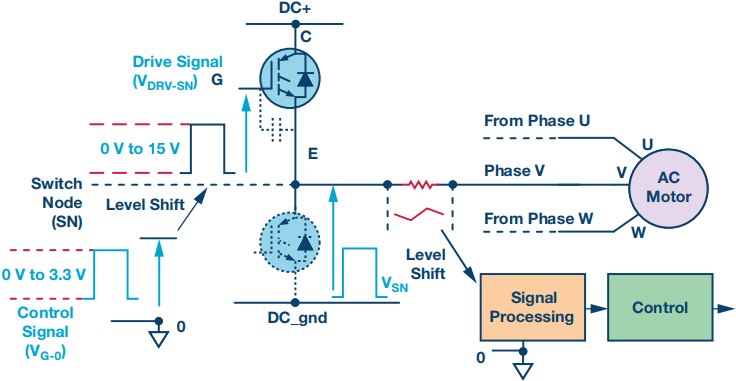
Figure 2 depicts a single inverter phase leg with the level shift and potential signal isolation requirements for the high-side gate driver signal and the phase current shunt measurement signal indicated.
Figure 2. In a 3-phase inverter leg, signal referencing is used.
Isolated Gate Drivers
The fundamental requirements of an isolated gate driver (as seen on Figure 2) include functional or safety isolation of the logic level switching signal, as well as an output driver capable of driving the IGBT gate voltage past the turn on and turn off thresholds to switch the IGBT at the required time instants while minimizing device switching loss, conduction loss, and EMI generation.
The IGBTs in 3-phase AC Inverters are controlled in antiphase, so that the high-side and low-side IGBTs are never on at the same time, even for a brief moment. This necessitates the addition of a short dead time period between the high- and low-side switching signals. Reduced dead time is critical for both system performance and IGBT protection.
Turning on an IGBT necessitates driving the IGBT into the saturation region, where conduction losses are minimized. This typically implies turn on voltages of greater than 12 V. IGBT turn off necessitates driving the IGBT to the cutoff region of operation in order for it to successfully block the reverse high voltage across it once the high-side IGBT has turned on.
In theory, this can be accomplished by lowering the IGBT gate emitter voltage to 0 V; however, when the high-side transistor is turned on, a secondary effect must be considered. A transient induced current flows in the low-side IGBT parasitic Miller capacitance (CGD in Figure) as a result of the switch node voltage rapidly changing.
This current flows through the low-side gate driver’s turn-off impedance (ZDRIVER in Figure 3), causing a transient voltage bounce at the gate emitter terminals of the low-side IGBT, as shown. If this voltage exceeds the IGBT threshold voltage, VTH, it can result in a brief turn on of the low-side IGBT, resulting in a transient shoot through of the inverter leg, increasing power dissipation and compromising reliability.
Figure 3. In IGBT switching, there is a Miller effect.
In general, there are two approaches to dealing with induced turn on of inverter IGBTs: using bipolar supplies and/or adding a Miller clamp. The ability of the isolated side of the driver gate to accept a bipolar power supply provides additional headroom for the induced voltage transient.
A negative supply rail of 7.5 V, for example, means that an induced voltage transient of >8.5 V is usually required to induce a spurious turn on. This is usually enough to prevent a false turn on.
A complementary approach is to reduce the gate driver circuit’s turn off impedance for a period of time after the turn off transition has been completed. This is referred to as a Miller clamp circuit. Because the capacitive current is now flowing in a lower impedance circuit, the magnitude of the voltage transient is reduced.
Asymmetric gate resistors for turn on and turn off can provide additional flexibility in controlling switching rates. All of these driver gate functions improve overall system reliability and efficiency.
In most servo drives, overcurrent protection is implemented at multiple levels. The drive protection scheme may include a distinction between sustained and transient overcurrents, with different trip levels and time constants for these overcurrent events.
Normally, this type of overcurrent protection is implemented using current measurement. It can be beneficial to have a fast acting protection mechanism integrated within the gate driver for very rapid and potentially catastrophic overcurrent events, such as short circuits on iAC Inverters outputs.
Desaturation protection is achieved by monitoring the collector emitter voltage of an IGBT while it is turned on. While the IGBT is saturated, the on-state voltage is a function of the current level within the IGBT, and this protection function can be configured to trigger a fault and rapidly turn off the IGBT if the on-state voltage exceeds an acceptable level.
The protection circuit does not monitor the IGBT’s on-state voltage during a brief blanking period. This is included to prevent false triggering during turn-on due to the collector-emitter voltage transition and/or transient overcurrent during the turn-on event.
Increased motor voltage and current distortion are caused by the increased dead time requirement associated with optocoupler technology. This degrades performance by increasing torque ripple and vibration, as well as decreasing efficiency due to increased harmonic losses.
These distortion effects are especially noticeable in AC Inverters applications, where control loops are relatively low in performance; however, even in high performance drives with high bandwidth current and velocity control, dead time related distortion can be a limiting factor in very low speed performance.
Figure 4. Line to line motor voltage was measured at (a) 500 ns dead time and (b) 1μs dead time.
Takeaway
New international motor energy efficiency regulations are hastening the transition away from fixed speed, direct online induction motors and toward inverter-controlled machines. An IGBT gate drive and some form of current measurement are common requirements for protection in simple open-loop AC Inverters up to high fidelity current control in servo drives.
Precision in timing and measurement, as well as reliability and robustness, are becoming increasingly important in these circuits’ technology requirements. Signal isolation is a significant challenge in both implementation and system design within a regulatory framework.