

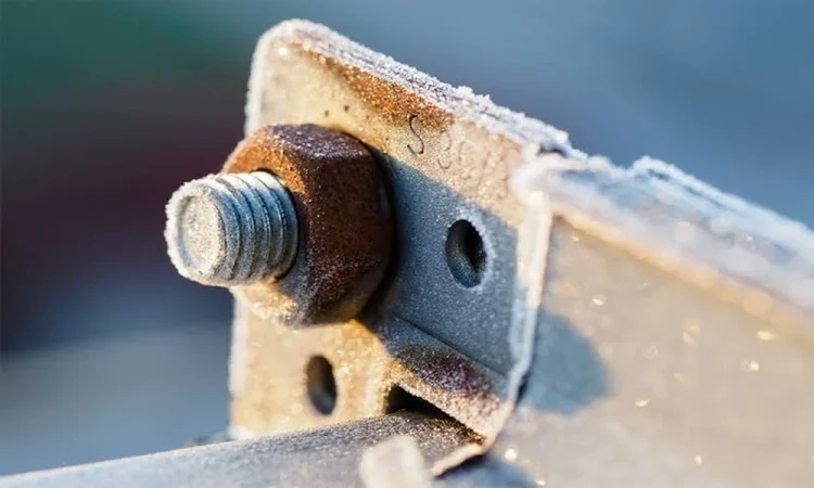

An aluminium equipment cover bolted to a steel support with stainless-steel fasteners looks straightforward on a drawing. In this hypothetical assembly, however, durability depends on details beyond the choice of each component: water collecting behind the cover, contact beneath a bolt head or a finish damaged during installation.
Mixed metals can perform well together. Bimetallic corrosion becomes a concern when the connection creates the conditions for it. For designers and maintenance teams, assessing the joint is more useful than judging the materials in isolation.
What allows bimetallic corrosion to occur?
Bimetallic corrosion, also called galvanic corrosion, requires three conditions: materials with different corrosion potentials, an electrical connection between them and an electrolyte linking their exposed surfaces. The electrolyte is a liquid that conducts through dissolved ions, such as salt-containing water.
The anodic material experiences accelerated corrosion; the other acts as the cathode. These roles describe behaviour in a particular environment rather than a universal ranking of durability.
As the British Stainless Steel Association explains, conductive moisture can bridge connected metals. A wet film containing dissolved contaminants can provide the liquid path without full immersion. Rainwater and condensation therefore deserve attention alongside obvious exposure to standing water.
Breaking electrical continuity or excluding the electrolyte interrupts the mechanism. Protection needs to remain effective as the assembly is installed, used and maintained.
Assess the whole joint, not just the metal pair
Sheet metal fabrication projects need a joint specification alongside component drawings, identifying the panels, supports, fasteners, washers and coatings that will meet in service.
Be precise about those materials. A note that simply says “steel” leaves important questions unanswered: exposed stainless steel, bare carbon steel and a zinc-coated surface present different conditions. Compare the installed parts with the specification, especially where repairs or substitutions have occurred.
Trace the electrical path through the assembly. In the equipment-cover example, a gasket could separate the aluminium panel from the steel support while the bolt still connects them. Contact can remain beneath the bolt head, along its shank or through a washer. A neighbouring bracket could also provide an indirect connection. The visible interface is only part of the assessment.
Next, follow the water. Check exposure to rain, condensation behind the cover and washdown water arriving from other directions. Salt contamination can increase conductivity. Sheltered pockets can remain damp after exposed surfaces dry, giving the back of a panel a different environment from its outward-facing surface.
Relative exposed areas matter too. A small anodic surface coupled to a much larger cathodic surface can suffer concentrated attack, a principle addressed in TWI’s corrosion guidance. Compare the surfaces participating in the wetted connection rather than the overall component dimensions. Coatings and local damage can change that relationship.
Galvanic-series charts help screen material combinations. Check the environment behind the ranking: seawater data will not automatically describe an intermittently damp indoor fixture. Protective surface films and exposure conditions affect behaviour, so use the chart to inform an assessment rather than predict service life.
Choose protection that addresses the actual risk
Material selection, electrical isolation, coatings and moisture management tackle different parts of the problem. The joint assessment should establish which measures are needed and how they work together.
Where the design permits, compatible materials can reduce reliance on isolation. Stainless-steel fasteners in aluminium still require consideration of exposure, geometry and protection, rather than blanket approval based on the material names.
For electrical isolation, examine every conductive path. An insulating washer addresses one contact point; separation elsewhere may require a gasket between mating faces and a sleeve around the bolt shank. The arrangement should account for the whole connection, including any alternative path through adjacent components.
An insulating material must meet both electrical and mechanical requirements, including the demands of compression, temperature and weather exposure. Deterioration or movement that allows the connection to loosen undermines the protection.
Paint and powder coating can limit exposure or separate surfaces when coverage remains intact. Handling, bolt tightening, drilling and cutting can expose metal, including at places where water collects. Installation details belong in the coating specification, alongside the finish itself.
Pay particular attention when coating only the anodic component. A small defect can expose a limited anodic area while a larger cathodic surface remains in contact with the same electrolyte, concentrating attack at the defect. Assess coating continuity and likely damage as well as nominal thickness.
Specify protection appropriate to both materials and their exposure, including mating faces that will become inaccessible, installation damage and a suitable repair approach. Resolve those details before the joint is assembled.
Moisture management starts with the shape of the detail. Avoid water-retaining pockets and overlaps that trap debris; preserve access for inspection. Follow the route of washdown water as carefully as rain running down the outer face.
Seals need their own assessment. A poorly executed seal can trap moisture behind it. Establish where the design excludes water, where any water can drain and how seals or protective layers will be checked.
Inspect for changes after installation
The original drawing can become an incomplete guide to the installed joint. Replacement fixings with a different material or finish, coatings scratched during maintenance and deteriorating insulating barriers can alter its behaviour. Record these changes so that future assessments reflect the current assembly.
Look for pitting, local metal loss, lifting finishes, deposits and staining around connections. Their distribution helps direct investigation, but appearance alone cannot identify the corrosion mechanism. Staining may arrive in runoff from another component. Crevice corrosion can develop in restricted, moisture-retaining spaces, including beneath washers.
For the hypothetical equipment cover, a useful inspection record would include:
- Specified and installed materials, including replacement fixings.
- Photographs locating deposits, coating damage and visible metal loss.
- Evidence of water retention, condensation or contamination.
- The condition of accessible gaskets, washers and sleeves.
- Previous repairs and any recurrence of damage.
Record the evidence before cleaning or repainting. A tidier surface can conceal the pattern that helps explain the cause, while the underlying conditions remain unchanged.
Set inspection frequency according to exposure, the consequences of failure and relevant maintenance guidance. A universal interval would overlook the difference between a sheltered cover and a connection exposed to salt-containing moisture.
Where isolation is part of the design, visual inspection assesses the condition of accessible barriers. Establishing electrical separation may also require testing under an appropriate procedure by competent personnel. Gaps in documentation should prompt checks of the installed detail rather than assumptions about its protection.
Know when the connection needs specialist assessment
Visible section loss, damaged fasteners or deterioration in a load-bearing connection call for engineering assessment. Seek competent advice where remaining capacity is uncertain, and corrosion expertise where the mechanism or suitable protection is unclear.
Required earthing or electrical bonding must remain intact. Interrupting a galvanic path is not a reason to remove an electrical safety provision; equipment repairs may need coordination between mechanical and electrical specialists.
Give the assessor the material specification, joint detail, exposure history and inspection record. The repair proposal should identify what it changes: the materials, electrical path, moisture exposure or protective surfaces. It should also specify how that change will be maintained and inspected.